Google
Grid Generation: 11/01/2006 - 12/01/2006

Tuesday, November 07, 2006

Unstructured 2D Triangular Mesh Matlab

Hello all,


For most of the Numerical simulations Unstructured Mesh are most favourable ones. Especially for Finite Element methods triangular delaunay meshes are used quite a lot. Today I am going to descibe about unstructured Mesh generation in MATLAB.

A typical Unstructured mesh in 2D looks like figure 1.

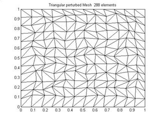
Figure 1 Unstructured Mesh


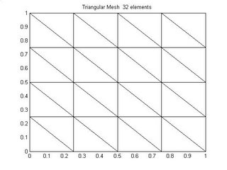
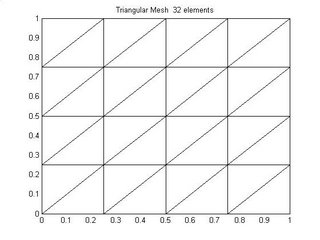
Triangular meshs can also be structured triangular with triangulation in some particular direction as shown in figure 2 and figure 3.


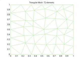
The Unstructured mesh shown in Figure 1 is basically made by randomly perturbing the nodes of a unifrom triangular mesh and it look very much like a delaunay mesh. Figure 4 shows a unstructured triangular delaunay mesh.


Now comming to How to generate shuch kind of meshes. I will here give a simple example of generating regular structured triangular mesh.

The code below is used to create the above triangular structured mesh

x=[0:1/(numx):1];

y=[0:1/(numy):1]; %Matlab's meshgrid is used to create 2D grid from specified divisons above
[X,Y] = meshgrid(x,y);


X1=reshape(X',length(x)*length(y),1);

Y1=reshape(Y',length(x)*length(y),1); %Coordinates of the node

node=[X1 Y1]; % Node
tri = triangulate(X1,Y1,element); % element connectivity

nele = size(tri,1);

Z= zeros(length(y)-2,length(x)-2);

nn = tri; % nodes in a long list

xx = X1(nn); yy = Y1(nn); % coordinates corresponding to nodes

xplot = reshape(xx,size(tri));

yplot = reshape(yy,size(tri));figure(1);

clf;

fill(xplot',yplot','w');

title(['Triangular Mesh ', num2str(length(nn)),' elements'])

%%%%%%Subfunction % triangulate


function tri = triangulate(xnod,ynod,nodes)
%
% tri = triangulate(xnod,ynod,nodes)
%
% triangulate the quadrilateral mesh
%

nele = size(nodes,1);
tri = zeros(3,2*nele)';
iv = [];
ii1 = [2 3 1];
jj1 = [4 1 3];
ii2 = [1 2 4];
jj2 = [2 3 4];
nrtri = 0;
for iel = 1:nele
iv = nodes(iel,:);
d1 = norm([xnod(iv(1))-xnod(iv(3));ynod(iv(1))-ynod(iv(3))]);
d2 = norm([xnod(iv(2))-xnod(iv(4));ynod(iv(2))-ynod(iv(4))]);
if d1 <= d2
nrtri = nrtri+1;
tri(nrtri,:) = iv(ii1);
nrtri = nrtri+1;
tri(nrtri,:) = iv(jj1);
else
nrtri = nrtri+1;
tri(nrtri,:) = iv(ii2);
nrtri = nrtri+1;
tri(nrtri,:) = iv(jj2);
end
end


This code will enable any one to generate a regular triangular mesh and different changes can be made to this code to get other kind of Triangular meshes as shown in figure 1 -4

Wednesday, November 01, 2006

Mesh Generation Using MATLAB Delaunay Function

If you are using Matlab Delaunay function to generate a unstructured 2D or 3D mesh you will land up in some sort of trouble. For very simple reasons. Have a look at the following piece of MATLAB code.
This code is to generate 3D tetrahedral mesh using the Matlab function Delaunay
x=[(0):1/(numx):(1)]; % numx=numy=numz = 1 (typical cube)
y=[(0):1/(numy):(1)];
z=[(0):1/(numz):(1)];
[X,Y,Z] = meshgrid(x,y,z);
X = [X(:)];
Y= [Y(:)];
Z = [Z(:)];
Tes = delaunay3(X,Y,Z);
L = [X(:) Y(:) Z(:)];
tetramesh1(Tes,L);camorbit(20,0) ;

This gives me a tetrahedral mesh with 'Tes' having the nodal connectivity matrix for a typical case (a cube with 6-tetrahedra, 8 nodes)it looks like
Tes = 4 7 8 6
1 5 7 6
2 4 7 6
2 1 7 6
2 4 7 3
2 1 7 3
Now if you are not care full you might land up in trouble. The reason being that output of delaunay function is in a random order some of the tessellation are arranged in clock wise direction and some in anticlockwise direction. So you need to reorder the tessellation in a particluar oder keeping one/summit node fixed and arranging others in clockwise or anticlcokwise direction.
Same thing happens in 2D. Now you can either do that if you are fond of MATLAB function Delaunay or you can use fowllowing piece of code given to me by some one who is master in tetrahedral meshes.


function [vertices,tess]=tess_lat(varargin)
% tess_lat: simplicial tessellation of a rectangular lattice
% usage: [tessellation,vertices]=tess_lat(p1,p2,p3,...)
%
% arguments: input
% p1,p2,p3,... - numeric vectors defining the lattice in
% each dimension.
% Each vector must be of length >= 1
%
% arguments: (output)
% vertices - factorial lattice created from (p1,p2,p3,...)
% Each row of this array is one node in the lattice
% tess - integer array defining simplexes as references to
% rows of "vertices".


% dimension of the lattice
n = length(varargin);


% create a single n-d hypercube
% list of vertices of the cube itself
vhc=('1'==dec2bin(0:(2^n-1)));
% permutations of the integers 1:n
p=perms(1:n);
nt=factorial(n);
thc=zeros(nt,n+1);
for i=1:nt
thc(i,:)=find(all(diff(vhc(:,p(i,:)),[],2)>=0,2))';
end


% build the complete lattice
nodecount = cellfun('length',varargin);
if any(nodecount<2)
error 'Each dimension must be of size 2 or more.'
end
vertices = lattice(varargin{:});


% unrolled index into each hyper-rectangle in the lattice
ind = cell(1,n);
for i=1:n
ind{i} = 0:(nodecount(i)-2);
end
ind = lattice(ind{:});
k = cumprod([1,nodecount(1:(end-1))]);
ind = 1+ind*k';
nind = length(ind);


offset=vhc*k';
tess=zeros(nt*nind,n+1);
L=(1:nind)';
for i=1:nt
tess(L,:)=repmat(ind,1,n+1)+repmat(offset(thc(i,:))',nind,1);
L=L+nind;
end


% ======== subfunction ========
function g = lattice(varargin)
% generate a factorial lattice in n variables
n=nargin;
sizes = cellfun('length',varargin);
c=cell(1,n);
[c{1:n}]=ndgrid(varargin{:});
g=zeros(prod(sizes),n);
for i=1:n
g(:,i)=c{i}(:);
end

In the next post I will discuss how you can get boundary nodes in a much easier fashion for any kind of meshes by using Faces in 3D.

Element Connectivity for the Hex Mesh : Mesh generation using MATLAB

In the Last post it was defined how to creat a basic Hex mesh in Matlab. What though was missing from the Post was how to get the element connectivity which needs to be Fed to the function which calculates the face connectivity.

So here are few simple steps by which you can easily get the Element Connectivites for the Basic Hexahedral Mesh while using MATLAB.


function element=make_elem(node_pattern,num_u,num_v,num_w,inc_u,inc_v,inc_w,nnx)

%
% Synopsis: element = make_elem(node_pattern,num_u,num_v,num_w,inc_u,inc_v,inc_w,nnx)
%
% Input: node_pattern > Natural node ordering for elements
% node_pattern=[ 1 2 nnx+1 nnx+2 nny+1 nny+2 nny+nnx+1 nny+nnx+2 ]; % Node pattern 1 %2 3 4 5 6 7 8 % according to me notations

% num_u > Number of control volumes in X direction.
% num_v > Number of control volumes in Y direction.
% inc_u > Increment in cell numbers in X direction
% inc_v > Increment in cell numbers in Y direction
%
% Output: element > Element connectivity matrix.


inc=[zeros(1,size(node_pattern,2))];
e=1;
element=zeros(num_u*num_v*num_w,size(node_pattern,2));

for row=1:num_v*num_u
for col=1:num_u
element(e,:)=node_pattern+inc;
inc=inc+inc_u;
e=e+1;
end
inc = row*inc_v;
if mod(e-1,num_u*num_v)==0
node_pattern = node_pattern + nnx;
end
end


% These few simple Steps will help any one who wants to get a basic Hex mesh using MATLAB

Few Tips on Mesh Generation in 3D Using Matlab

3D meshes/girds can be made from different type of mesh elements.

1.) Hexahedral Mesh elements.
2.) Tetrahedral Mesh elements.
3.) Pyramid Shape Mesh elements.
4.) Prism Types of Mesh elements.

Now if you can visualize it is always possible to decompose a basic hexahedral element into 3-Pyramid element, 2-Prism elements, 6-Tetra hedral elements and offcourse Hex is there as always.

So this means that it is always possible to create different kind of meshes using a Basic Hex mesh element. In MATLAB it is very easy to make a hex mesh u can follow these simple steps and u will get a Hex mesh.

%%%%%%%%%%%%%%%%%%%%%%%%%%%%%%%%%%%%%%%%%%%%%%%%%%%%%%%%%%%%%%%%%%%
x = [0:1/numx:1];
y = [0:1/numy:1];
z = [0:1/numz:1];

%Where numx, numy and numz are the number of basic hex elements u want in x, y and z %Direction.

%then follow the following step

[X Y Z] = meshgrid(x,y,z);

X = X(:);Y=Y(:);Z=Z(:);
%and then to plot the mesh you need following lines of code

node = [X Y Z];

figure(1);

if sloped==1
patch('Vertices',node,'Faces',faces,...
'FaceVertexCData',hsv(1),'FaceColor','none')
else
patch('Vertices',node,'Faces',faces,...
'FaceVertexCData',hsv(1),'FaceColor','none')
end
view(3); axis square

title(['Cartesian Mesh ', num2str(numx,3),'x',num2str(numy,3),'x',num2str(numz,3)])

% Now here one thing which you need to Compute is the Face connectivites which shoud %be fed into the function Patch which basically patches the different faces of the %hex and there by makes a complete Hexa Hedra. Now to get the Face connectivties you %need to use the following piece of code.

function faces = face_connectivity(num_u,num_v,num_w)


numx = num_u;
numy = num_v;
numz = num_w;

nnodex = numx+1;
nnodey = numy+1;
nnodez = numz+1;

face_pattern = [1 2 nnodex+2 nnodex+1]; % This is your face connectivity Pattern

nnx = numx+1 ;
nny = (nnodex)*(nnodey) ;
inc_u = 1;
inc_v = nnx;
inc_w = nny;
node_pattern=[ 1 2 nnx+2 nnx+1 nny+1 nny+2 nny+nnx+2 nny+nnx+1 ]; % Node connectivity
element = zeros(numx*numy*numz,8);
element = make_elem_hexa(node_pattern,numx,numy,numz,inc_u,inc_v,inc_w,nnx);

% ThisFunction gives the element connectivity.

faces = zeros(1,4);
face = zeros(6,4);
face1 = [1 2 3 4];
face2 = [4 3 7 8];
face3 = [5 6 7 8];
face4 = [2 6 7 3];
face5 = [1 5 8 4];
face6 = [1 2 6 5];

[m,n] = size(element);

for i = 1:size(element,1)

face = [element(i,face1);element(i,face2);element(i,face3);element(i,face4);element(i,face5);element(i,face6)];
faces = cat(1,faces,face);
end

faces(1,:) = [];
faces = faces;